\begin{center}
\huge{\textbf{Lab 2 Report}}\
\text{ECE 124}\
\text{Group 3 - Session 203}\
\textbf{Yashashwin Karthikeyan}\
\texttt{LS203\char_T03\char_Lab2\char_REPORT\char_Yashashwin\char`_Karthikeyan}
\end{center}
\newpage
Top level file: LogicalStep_Lab2_top.vhd
--- Author: Group 3 - Yashashwin Karthikeyan and Roozbeh Ali
library ieee;
use ieee.std_logic_1164.all;
use ieee.numeric_std.all;

entity LogicalStep_Lab2_top is port (
    clkin_50    : in std_logic;                      -- 50MHz clock input
    pb_n        : in std_logic_vector(3 downto 0);   -- push-button inputs
    sw          : in std_logic_vector(7 downto 0);   -- The switch inputs
    leds        : out std_logic_vector(7 downto 0);  -- for displaying the switch content
    seg7_data 	: out std_logic_vector(6 downto 0);  -- 7-bit output to 7-segment
    seg7_char1  : out std_logic;                     -- seg7 digit 1 output
    seg7_char2  : out std_logic                      -- seg7 digit 2 output
);
end LogicalStep_Lab2_top;

architecture SimpleCircuit of LogicalStep_Lab2_top is

    --Seven segment decoder component
    --Consumes hex values (in binary format) as input
    --Outputs 7-bit pattern
    component SevenSegment port (
        hex         :  in  std_logic_vector(3 downto 0);
        sevenseg    :  out std_logic_vector(6 downto 0)
    );
    end component;

    --Seven segment mux component
    component segment7_mux port (
        clk     : in std_logic := '0';
        DIN2    : in std_logic_vector(6 downto 0);
        DIN1    : in std_logic_vector(6 downto 0);
        DOUT    : out std_logic_vector(6 downto 0);
        DIG2    : out std_logic;
        DIG1    : out std_logic
    );
    end component;

    --PB-Inverters component
    --LogicalStep board is active-low input.
    --This invertor component maps the active-low push-button inputs to an active-high signal
    component PB_Inverters is port (
        pb_n: in std_logic_vector(3 downto 0);
        pb:   out std_logic_vector(3 downto 0)
    );
    end component;

    --logic_proc component
    --Performs logical operations (AND, OR, XOR, XNOR) on the sw inputs.
    --Takes in two 4-bit logic vectors and one 2-bit select line
    --Performs different logic operations based on the select input.
    --Output is directed to `logic_out` signal.
    component logic_proc is port (
        logic_in0, logic_in1    :in std_logic_vector(3 downto 0);
        select_line             :in std_logic_vector(1 downto 0);
        logic_out               :out std_logic_vector(3 downto 0)
    );
    end component;

    --4 bit full adder component
    --Takes in two 4-bit logic vectors and a 1-bit carry-in value.
    --Returns sum and carry output by adding the two input vectors.
    component full_adder_4bit is port (
        INPUT_B         : in std_logic_vector(3 downto 0);
        INPUT_A         : in std_logic_vector(3 downto 0);
        CARRY_IN        : in std_logic;
        FA_CARRY_OUT    : out std_logic;
        FA_SUM_OUT      : out std_logic_vector(3 downto 0)
    );
    end component;

    --Result mux component
    --Takes in the result of adder (4-bit), the input digit (4-bit) and a select line (1 bit).
    --Outputs the result or input digit based on the select line.
    --Used to switch between displaying adder result and input digits on the 7-segment.
    component result_mux is port (
        IN_ADDER : in std_logic_vector(3 downto 0);
        IN_DIG   : in std_logic_vector(3 downto 0);
        IN_SEL   : in std_logic;
        OUT_VAL  : out std_logic_vector(3 downto 0)
    );
    end component;

    --Decleration of various intermediary signals used
    --to direct signals between different component instances.

    --temporary signal used to store result of SevenSegment decoder
    signal seg7_A: std_logic_vector(6 downto 0);
    -- 4-bit input signal used to get the hex values from sw(3 downto 0) switches
    signal hex_A: std_logic_vector(3 downto 0);

    --temporary signal used to store result of SevenSegment decoder
    signal seg7_B: std_logic_vector(6 downto 0);
    -- 4-bit input signal used to get the hex values from sw(7 downto 4) switches
    signal hex_B: std_logic_vector(3 downto 0);

    --signal used to refer to the inverted inputs from the pushbuttons.
    signal pb: std_logic_vector(3 downto 0);

    --stores adder result.
    signal sum_dig_1: std_logic_vector(3 downto 0);
    --used as final input for into the 7segment display (panel-A)
    signal display_dig_1: std_logic_vector(3 downto 0);
    --used as final input for into the 7segment display (panel-B)
    signal display_dig_2: std_logic_vector(3 downto 0);

    signal signal_carry: std_logic;

begin

    hex_A <= sw(3 downto 0);
    hex_B <= sw(7 downto 4);

    --port map for 4-bit adder component
    INST1_4BIT_ADDER: full_adder_4bit port map(
        hex_A,
        hex_B,
        '0',
        signal_carry,
        sum_dig_1
    );

    --port map for result_mux component, 7 segment panel A
    INST1_RES_SUM: result_mux port map(
        sum_dig_1,
        hex_A,
        pb(2),
        display_dig_1
    );

    --port map for result_mux component, 7 segment panel B
    INST2_RES_SUM: result_mux port map(
        "000" & signal_carry,
        hex_B,
        pb(2),
        sum_dig_2
    );

    --port map for 7segment decoder, panel A
    INST1: SevenSegment port map(display_dig_1, seg7_A);
    --port map for 7segment decoder, panel B
    INST2: SevenSegment port map(sum_dig_2, seg7_B);

    --port map for 7segment-mux
    INST3: segment7_mux port map(
        clkin_50,
        seg7_A(6 downto 0),
        seg7_B(6 downto 0),
        seg7_data,
        seg7_char2,
        seg7_char1
    );

    --port map for pushbutton invertor
    PB_Inv_INST0: PB_Inverters port map(pb_n, pb);

    --port map logical operations
    Logic_Proc_INST0: logic_proc port map(
        hex_B,
        hex_A,
        pb(1 downto 0),
        leds(3 downto 0)
    );
end SimpleCircuit;
Subordinate file: full_adder_4bit.vhd
--- Author: Group 3 - Yashashwin Karthikeyan and Roozbeh Ali
library ieee;
use ieee.std_logic_1164.all;

entity full_adder_4bit is port (
    INPUT_B         : in std_logic_vector(3 downto 0);
    INPUT_A         : in std_logic_vector(3 downto 0);
    CARRY_IN        : in std_logic;
    FA_CARRY_OUT    : out std_logic;
    FA_SUM_OUT      : out std_logic_vector(3 downto 0)
);
end full_adder_4bit;

architecture full_adder_4bit of full_adder_4bit is

    --1-bit adder component
    component full_adder_1bit is port (
        INPUT_B         : in std_logic;
        INPUT_A         : in std_logic;
        CARRY_IN        : in std_logic;
        FA_CARRY_OUT    : out std_logic;
        FA_SUM_OUT      : out std_logic
    );
    end component;

    --temporary signals for channeling data between the 1-bit instances
    signal carry_1: std_logic;
    signal carry_2: std_logic;
    signal carry_3: std_logic;

begin

    --port maps for the 4 instances of 1-bit adder.
    INST1: full_adder_1bit port map(
        INPUT_A(0),
        INPUT_B(0),
        CARRY_IN,
        carry_1,
        FA_SUM_OUT(0)
    );
    INST2: full_adder_1bit port map(
        INPUT_A(1),
        INPUT_B(1),
        carry_1,
        carry_2,
        FA_SUM_OUT(1)
    );
    INST3: full_adder_1bit port map(
        INPUT_A(2),
        INPUT_B(2),
        carry_2,
        carry_3,
        FA_SUM_OUT(2)
    );
    INST4: full_adder_1bit port map(
        INPUT_A(3),
        INPUT_B(3),
        carry_3,
        FA_CARRY_OUT,
        FA_SUM_OUT(3)
    );
end full_adder_4bit;
Subordinate file: full_adder_1bit.vhd
-- Authors: Group 3 - Yashashwin Karthikeyan and Roozbeh Ali
library ieee;
use ieee.std_logic_1164.all;

entity full_adder_1bit is port (
    INPUT_B         : in std_logic;
    INPUT_A         : in std_logic;
    CARRY_IN        : in std_logic;
    FA_CARRY_OUT    : out std_logic;
    FA_SUM_OUT      : out std_logic
);
end full_adder_1bit;

architecture full_adder_1bit of full_adder_1bit is
    signal HA_CARRY_OUT: std_logic;
    signal HA_SUM_OUT: std_logic;

begin
    -- 1-bit adder implementation
    -- daisy-chained with multiple instances to build 4-bit adder.

    HA_CARRY_OUT <= INPUT_B AND INPUT_A;
    HA_SUM_OUT <= INPUT_B XOR INPUT_A;

    FA_CARRY_OUT <= (HA_SUM_OUT AND CARRY_IN) OR HA_CARRY_OUT;
    FA_SUM_OUT <= HA_SUM_OUT XOR CARRY_IN;

end full_adder_1bit;
Subordinate file: SevenSegment.vhd
--- Author: Group 3 - Yashashwin Karthikeyan and Roozbeh Ali
library ieee;
use ieee.std_logic_1164.all;
use ieee.numeric_std.all;

-------------------------------------------------------------------------
-- 7-segment display driver. It displays a 4-bit number on a 7-segment
-- This is created as an entity so that it can be reused many times easily

entity SevenSegment is port (
    hex         : in std_logic_vector(3 downto 0);   -- The 4 bit data to be displayed
    sevenseg    : out std_logic_vector(6 downto 0)   -- 7-bit outputs to a 7-segment
);
end SevenSegment;

architecture Behavioral of SevenSegment is

--
-- The following statements convert a 4-bit input, called dataIn to a pattern of 7 bits
-- The segment turns on when it is '1' otherwise '0'
--
begin
    --GFEDCBA
    with hex select
    sevenseg <= "0111111" when "0000",  -- [0]
        "0000110" when "0001",    -- [1]
        "1011011" when "0010",    -- [2]      +---- a -----+
        "1001111" when "0011",    -- [3]      |            |
        "1100110" when "0100",    -- [4]      |            |
        "1101101" when "0101",    -- [5]      f            b
        "1111101" when "0110",    -- [6]      |            |
        "0000111" when "0111",    -- [7]      |            |
        "1111111" when "1000",    -- [8]      +---- g -----+
        "1101111" when "1001",    -- [9]      |            |
        "1110111" when "1010",    -- [A]      |            |
        "1111100" when "1011",    -- [b]      e            c
        "1011000" when "1100",    -- [c]      |            |
        "1011110" when "1101",    -- [d]      |            |
        "1111001" when "1110",    -- [E]      +---- d -----+
        "1110001" when "1111",    -- [F]
        "0000000" when others;    -- [ ]
end architecture Behavioral;
\newpage
Subordinate file: logic_proc.vhd
--- Author: Group 3 - Yashashwin Karthikeyan and Roozbeh Ali
library ieee;
use ieee.std_logic_1164.all;

entity logic_proc is port (
    logic_in0, logic_in1 : in std_logic_vector(3 downto 0);
    select_line          : in std_logic_vector(1 downto 0);
    logic_out            : out std_logic_vector(3 downto 0)
);
end logic_proc;

architecture logic_mux of logic_proc is
begin

    --implementation of logic_proc component
    --4-bit inputs, 2-bit select line
    --lets us select between different logic operatins
    with select_line(1 downto 0) select
    logic_out <= (logic_in0 AND logic_in1) when "00",
        (logic_in0 OR logic_in1) when "01",
        (logic_in0 XOR logic_in1) when "10",
        (logic_in0 XNOR logic_in1) when "11";
end logic_mux;
Subordinate file: result_mux.vhd
--- Author: Group 3 - Yashashwin Karthikeyan and Roozbeh Ali
library ieee;
use ieee.std_logic_1164.all;
use ieee.numeric_std.all;

entity result_mux is port (
    IN_ADDER		: in std_logic_vector(3 downto 0);
    IN_DIG		: in std_logic_vector(3 downto 0);
    IN_SEL		: in std_logic;
    OUT_VAL		: out std_logic_vector(3 downto 0)
);
end result_mux;

architecture result_display of result_mux is
begin

    --implemantion of 2-to-1 mux
    --4 bit inputs, 1 bit select line.
    --enables switching between displaying adder result and the input digit.
    with IN_SEL select
    OUT_VAL <= IN_ADDER when '1',
    IN_DIG when '0';

end result_display;
Subordinate file: PB_Inverters.vhd
--- Author: Group 3 - Yashashwin Karthikeyan and Roozbeh Ali
library ieee;
use ieee.std_logic_1164.all;

entity PB_Inverters is port (
    pb_n: in std_logic_vector(3 downto 0);
    pb: out std_logic_vector(3 downto 0)
);
end PB_Inverters;

architecture inverter of PB_Inverters is
begin
    pb <= not pb_n; --inverts active-low signal to active-high output
end inverter;
Subordinate file: hex_mux.vhd
--Authors: Group 3 - Yashashwin Karthikeyan and Roozbeh Ali
library ieee;
use ieee.std_logic_1164.all;
entity hex_mux is port (
hex_num3, hex_num2, hex_num1, hex_num0 :in std_logic_vector(3 downto 0);
mux_select :in std_logic_vector(1 downto 0);
hex_out :out std_logic_vector(3 downto 0)
);
end hex_mux;
architecture mux_logic of hex_mux is
begin
--implemention of 4-to-1 mux
-- Four 4-bit inputs, 2-bit select line
with mux_select(1 downto 0) select
hex_out <= hex_num0 when "00",
hex_num1 when "01",
hex_num2 when "10",
hex_num3 when "11";
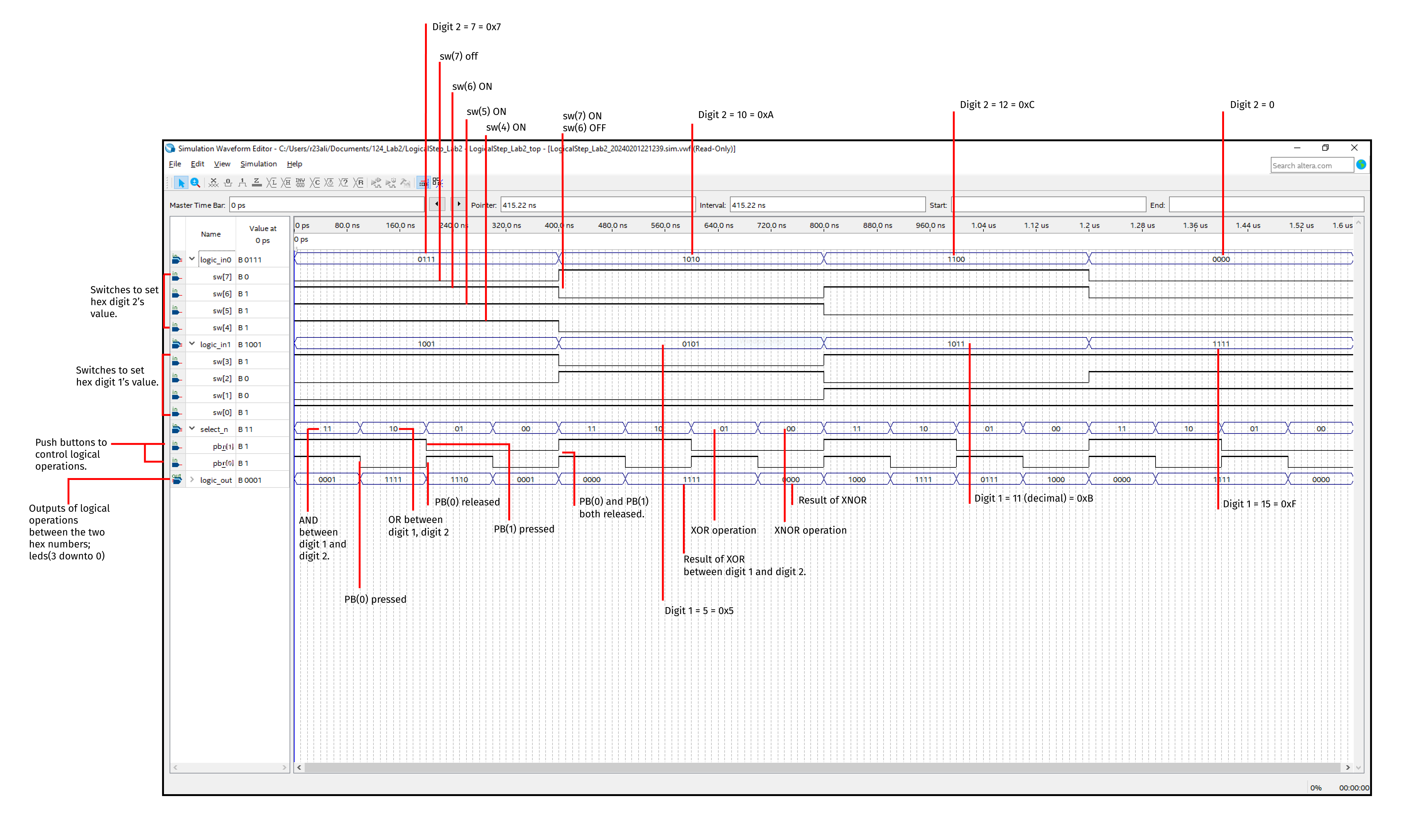
end mux_logic;Annotated Simulation Waveform
\begin{center} \text{END} \end{center}