- Split the datapath. The riscv instruction set, at the end of the day, is still just a spec. Someone needs to go and implement it on hardware.
- The datapaths describe how the different hardware units connect together and perform the operations based on the assembly instructions.
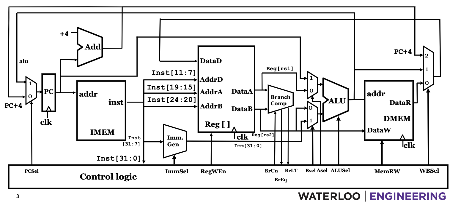
The Final Datapath
R-Type: register
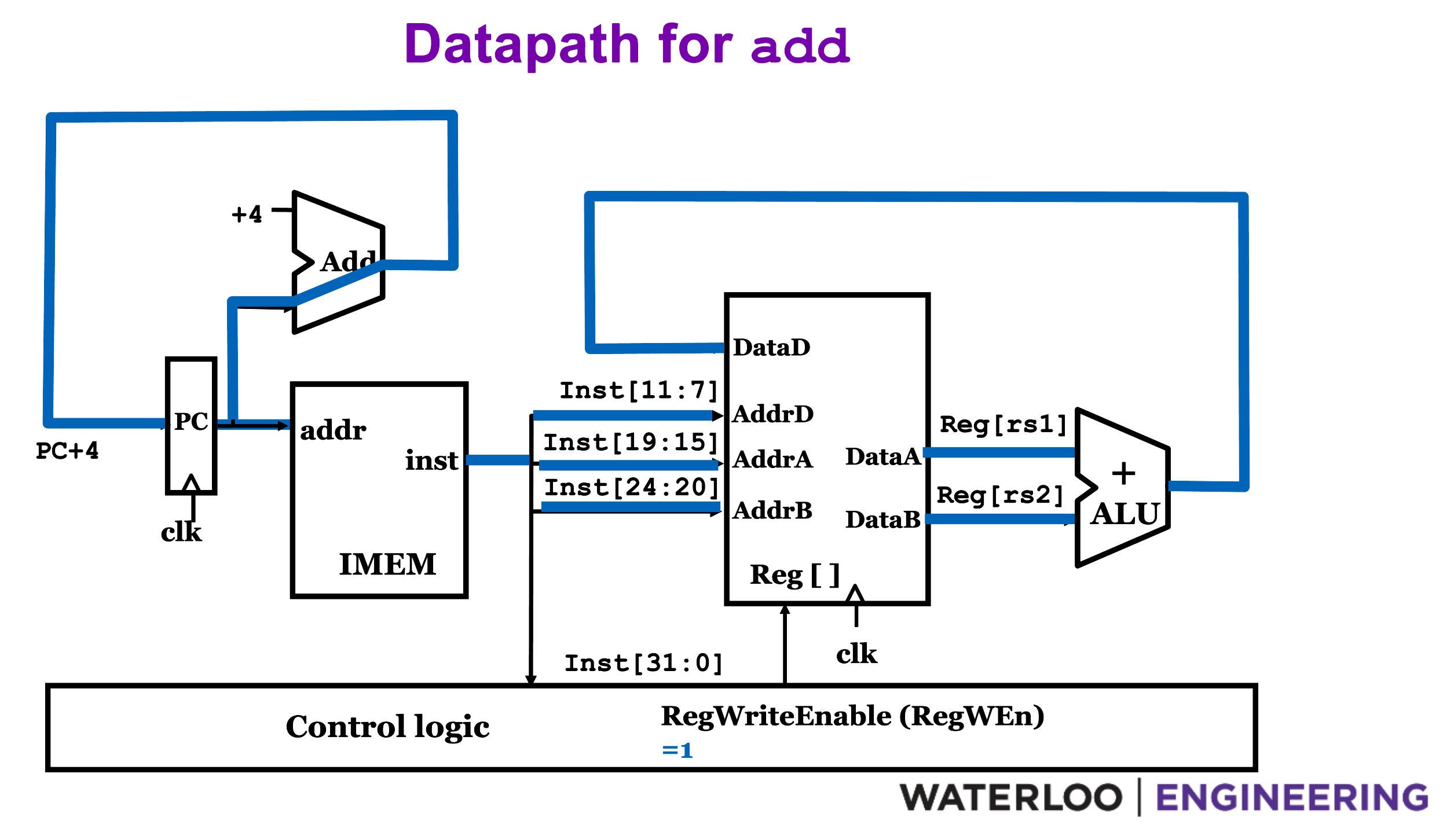
ADD
Performs two state changes
reg[rd] = reg[rs1] + reg[rs2]PC = PC + 4- Opcode:
0110011 - The registers are specified by the bits 15-19, 20-24, 7-11 of the instruction.
- The
PCis updated using an adder/ALU hardwired to only add. - We use
RegWriteEnableto letrdget updated.
SUB
- Very similar to
ADDbut we have a control signalALUSel = 1to negaterd2input before adding. ALUSelis generated usingfunct7 = 0100000forSUB
Other R-type

- R-type instructions perform simple operations implemented by the ALU.
- The control signals are generated based on the funct3, funct7.
- The exact signals generated depend on the ALU construction.
I-Type: immediate
Modifying ADD into ADDI
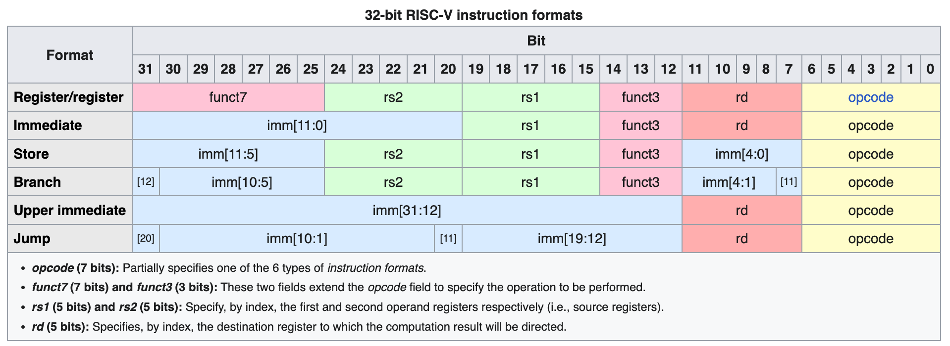
- Bits 20-31 specify a 12-bit immediate.
- We need a unit to sign extend it to 32 bits.
Imm. Sel = 1to enable it. - We need a way to choose the immediate instead of rs2.
BSel. - Other datapaths remain the same.
LW - Load Word
lw x2, 8(x1)
- Use ALU to add offset and
rs1to get address for memory access. MemRW = readto enable mem. reads.WBSelinto a mux choose what goes intord. Selecting between ALU output and memory block output.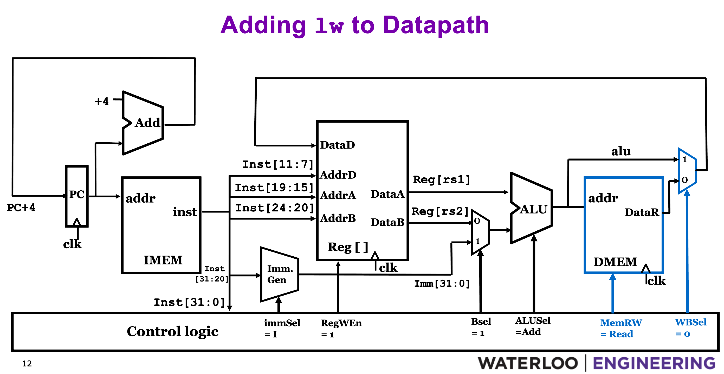
Other loads
func3encodes the size and signedness of the bytes to load.- Since wordsize = 32,
lb, lhrequire some additional gates to extract the right data and sign/0-extend based on (lbu, lhu).
jalr - jump and link register
jalr rd, imm(rs)
- Saves return address:
rd = PC + 4 - Jumps to address in register + offset:
PC = rs + imm - Usually used to jump to addr in register eg: returned from another function.
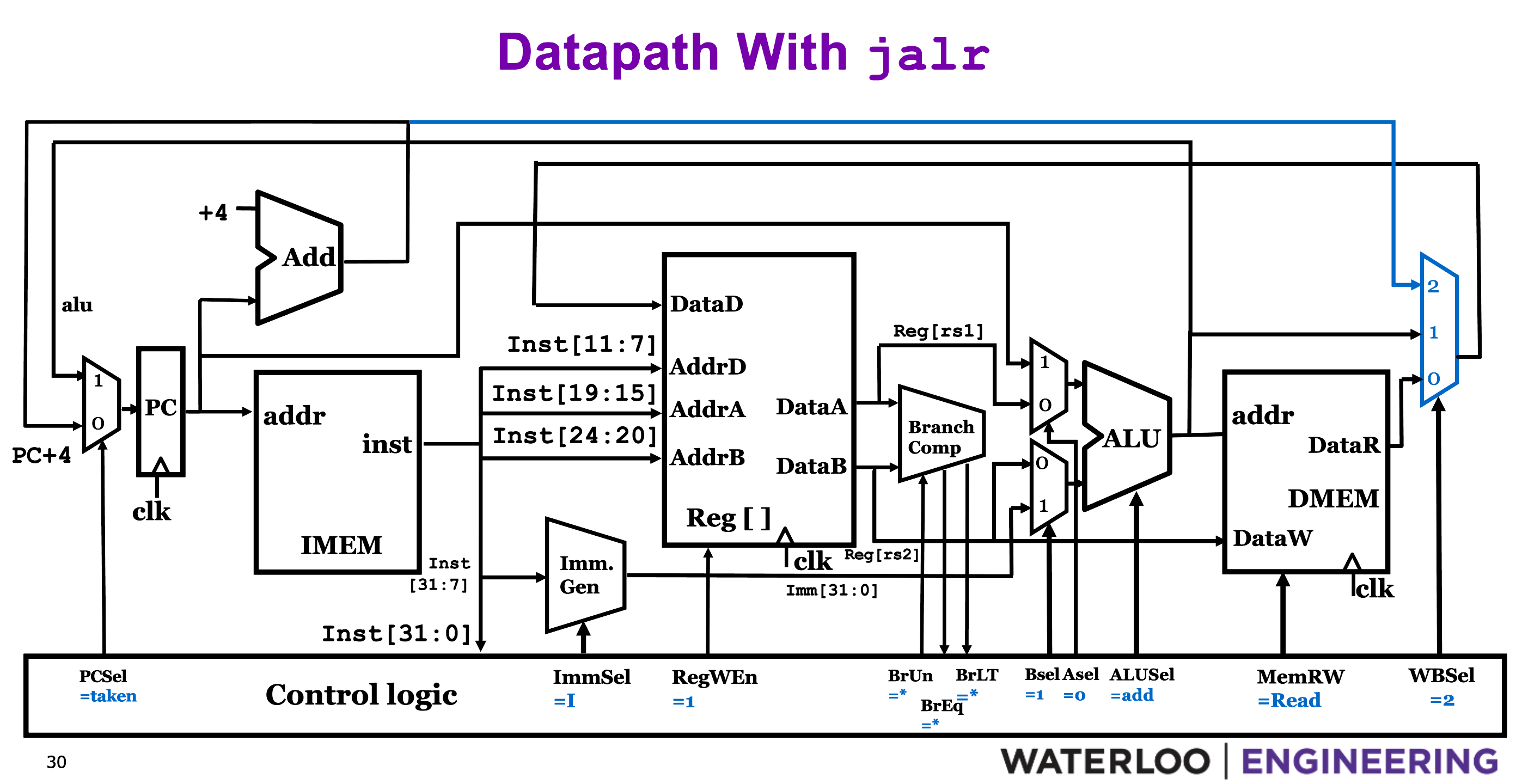
- Save the output of PC adder in
rd(regfile, PC + 4). - Set
PCSel = takento make the jump.
S-Type: store
rs1gives us base address in memory.immis split up and gives us memory offset.rs2gives the value to be stored in memory.
SW - store word
- We just need to pull a wire from the existing
rs2and feed it into the DMEM input. MemRW = writeWBSelcan be anything since there’s not register writeback.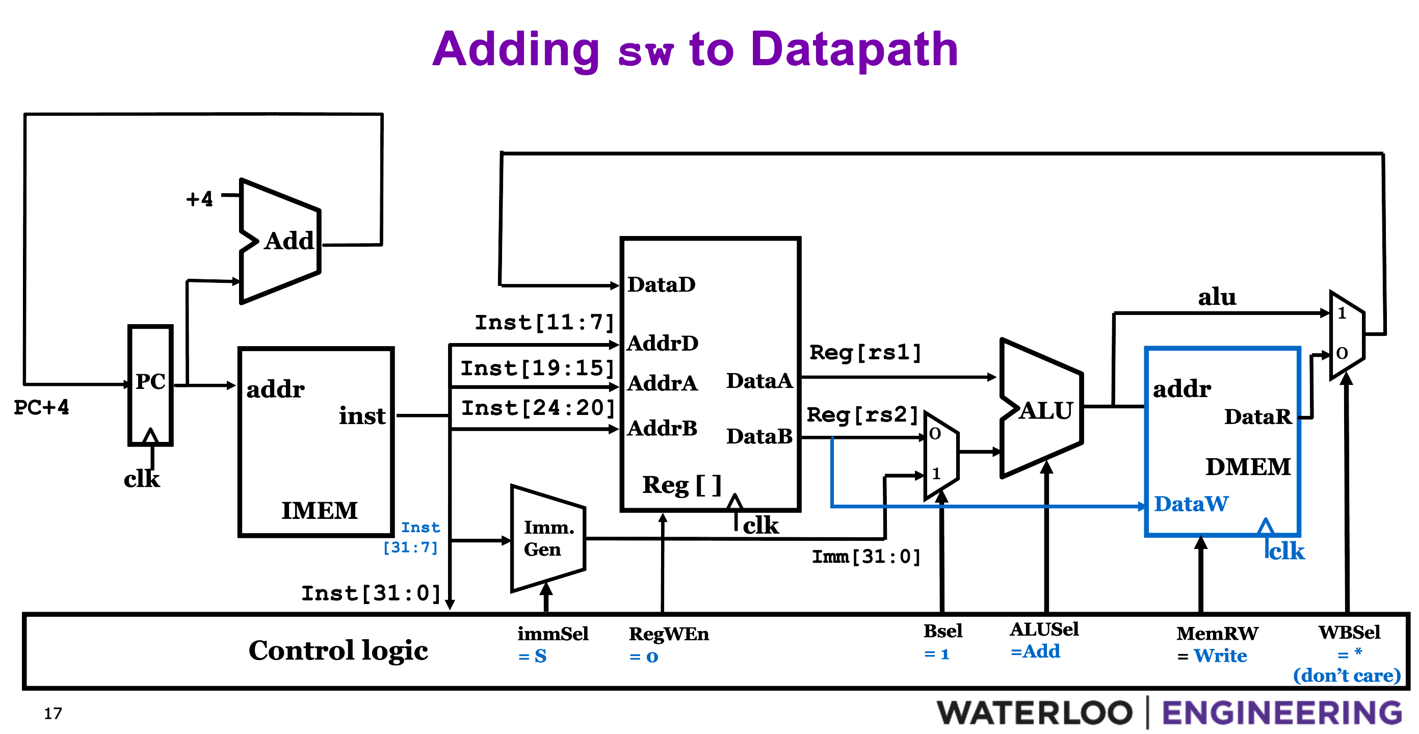
B-Type: branch
- Same fields as S-type but immediate is interpreted differently.
- 13-bit immediate (12 data, 1 sign) to represent jump destinations.
- 0-th bit is always 0 since jump locations are always even.
- So we can still manage with a 12-bit immediate.
State Changes:
PC = PC + 4 or PC + immediateif branch was taken.
Things to do while branching
-
Calculate
PC + immediate -
Compare
rs1, rs2and feed into mux to choose the correct branch dest. -
Branch comparator to compare the registers.
-
A mux with
PCSelto select PC value.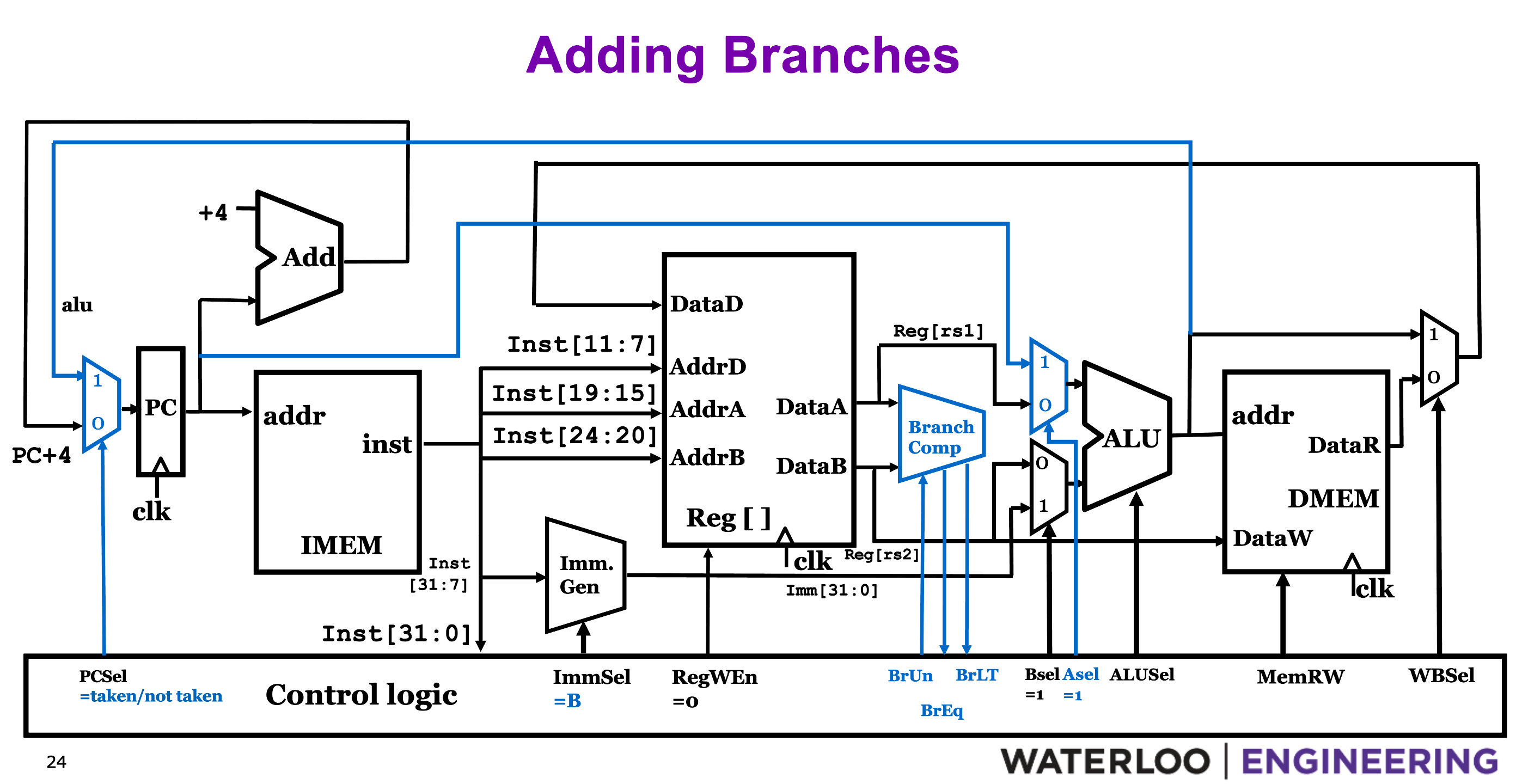
Branch Comparator
-
IN:
BrUn == 1- to compare unsigned. -
Out:
BrEq == 1 => rs1 == rs2 -
Out:
BrEq == 0 => rs1 != rs2 -
Out:
BrLT == 1 => rs1 < rs2 -
Out:
BrLT == 0 => rs1 >= rs2
J-Type: jumps
jal ra, Label
PC = PC + offset- pc relative addressing- much larger immediate field (20-bits) ⇒ locations, 2 byte apart.
- Change in datapath: add another selector in
Immediate Generation.
U-Type
- Params:
rd, 20-bit immediate.
lui - load upper immediate
- Similar to
addi, but larger immediate and also alu signals to shift to upper 20 bits.
auipc - add upper immediate to program counter
- Use the paths similar to branch to consume
PCinto ALU and perform sum.
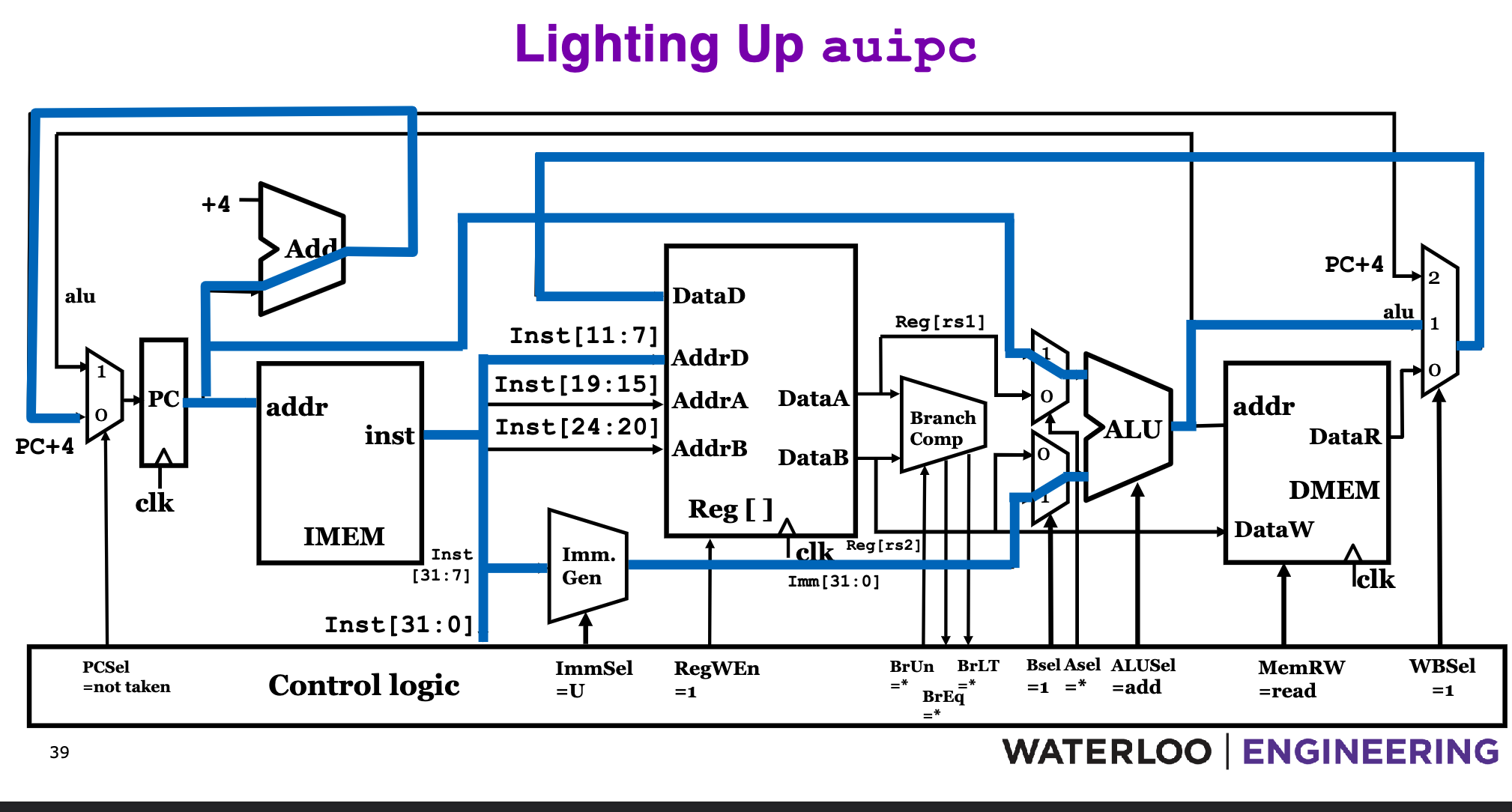
- typo:
ASel = 1to ensure PC gets fed into ALU.
Immediate Generation
ImmSelsignal to select which instruction bits represent the immediate.